Natural gas treating upstream of pipeline transportation
Natural gas is widely used as an inexpensive fuel with high heating capacity (burning single cubic meter of gas yields up to 54 400 kJ or 51500 btu). It is considered one of the best consumer and household fuels. Pipelines are the most prolific method of transporting the natural gas so far.
However, upstream of the main pipelines the gas has to be treated and conditioned so that it meets certain criteria. The most serious ones are hydrocarbon and water dew points. There are several ways to reach the strict requirements on these. Namely:
1. Low temperature separation (LTS)
The process provides the following:
- initial separation of gas and liquid components while capturing the liquid plugs in the inlet separator;
- cooling of the inlet stream in the gas/gas heat exchanger by the treated and cooled down gas;
- lowering the temperature of the gas by expanding the gas stream either by JT (Joule-Thompson) valve, Vortex tube, or a turbo-expander;
- following separation of the cooled down gas in the low-temperature separator;
- passing through the heat-exchanger to heat up the treated gas before entering the pipeline main.
2. Low temperature condensation (LTC)
The process provides the following:
- initial separation of gas and liquid components while capturing the liquid plugs in the inlet separator;
- cooling down the inlet gas stream in the heat exchanger by an outside source of cold such as air coolers or some sort of a chiller cycle;
- following separation of the cooled down gas in the low-temperature separator.
3. Absorption gas treating
The process provides the following:
- initial separation of gas and liquid components while capturing the liquid plugs in the inlet separator;
- absorption column where liquid absorbent captures the moisture and liquids remaining in the gas stream;
- discharge separator, where precipitation or separation of the absorbent takes place.
4. Adsorption gas treating
The process provides the following:
- initial separation of gas and liquid components while capturing the liquid plugs in the inlet separator;
- adsorption column, where solid adsorbent particles capture the moisture and liquids still present in the gas stream;
- discharge separating filter, where precipitation or separation of the adsorbent particles takes place.
Low-temperature separation (LTS)
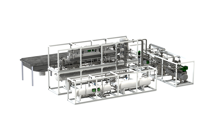
Natural gas production is specific in high initial pressures in a bed when production is only beginning. First gas will exit the well with a significant pressure of 100-150 bar and possibly higher. This free pressure can be inexpensively transformed into a source of cold by expanding the flow. It is only logical that under these conditions the easiest and most typical way of treating the gas is the low temperature separation method, where the amount of capex is minimal with satisfactory product characteristics. The method is also advantageous in its ease of operation and maintenance of the equipment involved. Standard process equipment in the case of LTS would comprise several pressure vessels (separators), some heat exchangers with piping and a JT valve (or a turboexpander).
The unit may be further enhanced to extract LPG out of the stabilized condensate.
Economic outcome of the proposed GazSurf solution
The project was implemented in three stages:
Stage 1. Chiller (source of cold) installation and commissioning, condensate stabilization in the existing degassing vessels/tanks.
Stage 2. Condensate stabilization column installation and commissioning.
Stage 3. LPG extraction installation and commissioning.
Table 4. Each stage increases the output, inviting additional value!
|
Project details |
1 stage |
2 stage |
3 stage |
All stages |
|
|---|---|---|---|---|---|
|
Construction |
|||||
|
Ball-park САРЕХ |
mln. rub. |
365 |
185 |
200 |
700 |
|
Project implementation period |
months |
8 |
6 |
6 |
10 |
|
Product yield increase upon commissioning of the stage |
|||||
|
LPG |
tons/year |
0 |
0 |
20000 |
- |
|
Gas condensate |
tons/year |
40000 |
15000 |
- |
- |
|
Total (revenue growth per year) |
mln. rub. |
700 |
263 |
300 |
1263 |
|
ROI from the start of the project (w/o the cost of finance) |
years |
1,19 |
1,20 |
1,17 |
1,22 |
The table demonstrates how each stage significantly increases the quantity of the extracted products leading to increase in revenue. However, by implementing all stages at once we get the larger overall ROI in the smaller timeframe. Therefore, despite larger capital investment, the investors get larger returns in the shorter time.
Conclusion
- Low temperature separation produces a more stable dew point characteristic of the treated gas compared to low temperature separation by mitigating the inlet gas varying pressure factor as well as seasonal ambient temperature fluctuations;
- Low temperature condensation allows to cool the gas further than low temperature separation therefore increasing the liquid product yield;
- Compared to degassing separation, application of fractionating columns allows to cut the emissions, reduces the amount of gas to flare and receives a wider range of liquid hydrocarbons products such as LPG, NGL, gas condensate etc.
- Despite increased capital expenditures implementation of these gas treatment project solutions provides shorter investment return periods both for the complex treating plant and for each stage of the project. Making it favorable for investors to spend their money on the complex project because the product yield (and ROI) will be substantially larger than the yields of separate project stages with comparable implementation periods.
GazSurf has a wealth of experience in implementation of such projects and filtering, dehydrating and complex associated petroleum and natural gas treating prior to the pipe transportations solutions in general. Our team is ready to help you with solving your gas treating tasks of any degree of complexity!
Methanol regeneration section
Responsible for methanol regeneration and pumping the regenerated methanol to the LTC heat exchangers nozzles.

Heating media heating and circulation section
Provides heat for the column reboiler and to methanol regeneration.
Fractionating (stabilization) section
Fractionating takes place in the condensate stabilization column. Stabilization is achieved by heating up the condensate inside the reboiler and heat-exchange process on the column’s process plates.
Low temperature condensation section
This section’s function is to cool down the gas further inside the recuperative heat exchangers and refrigerant vaporizer, after which the feed flow is separated into the gaseous and liquid fractions. The gas after separation and heating up in the recuperative heat exchanger is directed into the gas pipeline main, unstable condensate into the stabilizer column, and the water-methanol mixture into the methanol regeneration skid.
Process equipment of the unit may be broken down into the following sections:
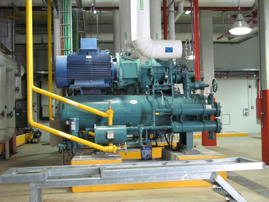
Chiller cycle section
Provides cooling down of the feed gas down to minus 250С. Cooling capacity of 900 кW (for minus −25 0С) is achieved by three screw refrigerant compressors. Refrigerant condensation takes place inside the air coolers. The group also comprises the following vessels: refrigerant accumulator, economizer. Chiller cycle function is to condense the liquid refrigerant and flow it into the vaporizer (plate-fin or pipe-in-kettle heat exchanger) where the feed gas is cooled down by refrigerant phase change.
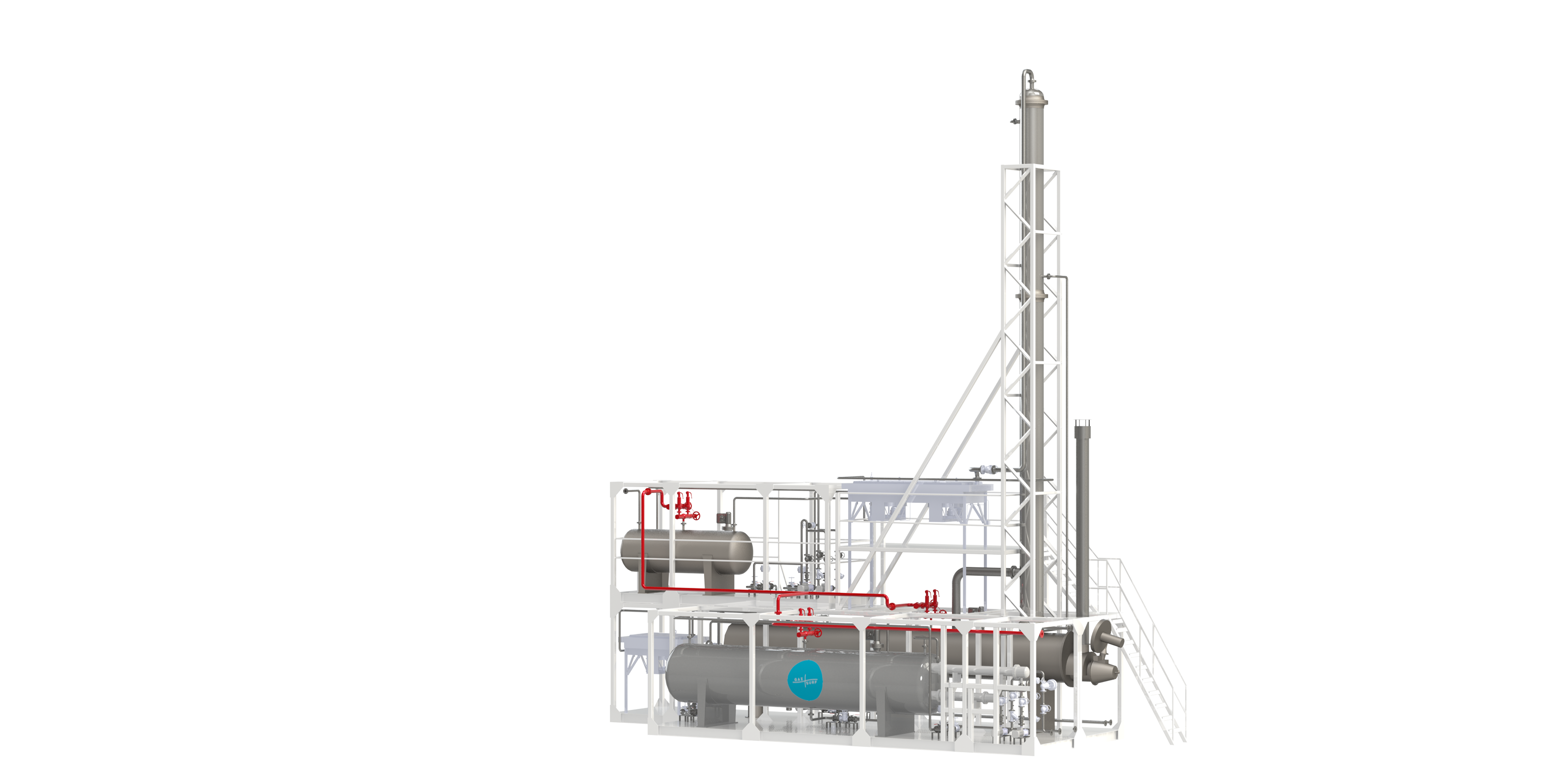
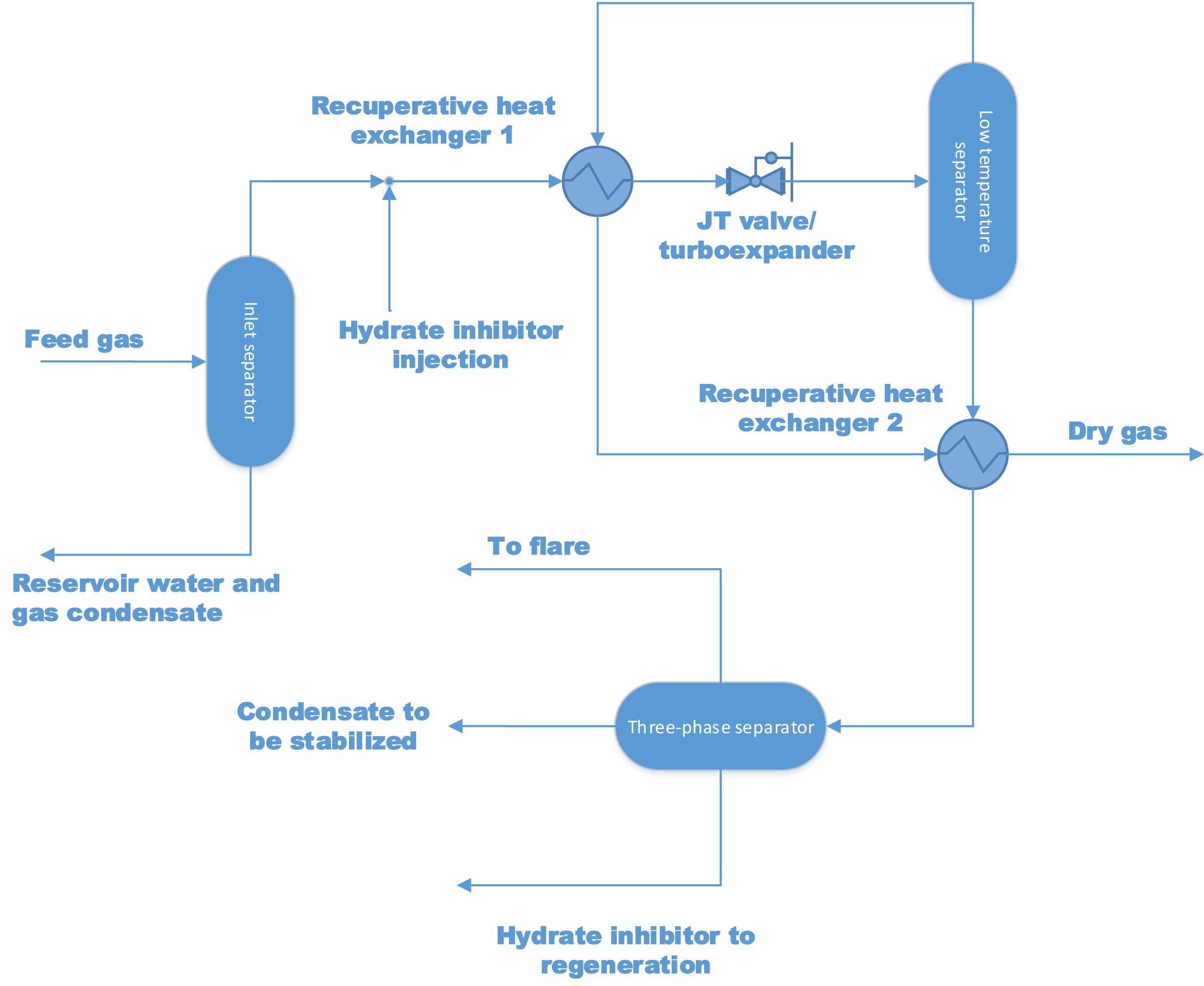
Typical low-temperature separation (LTS) unit process description
Raw feed gas from the well comes into the inlet separator, where liquids (reservoir water with dissolved inhibitors and liquid hydrocarbon condensate) are removed. Separated gas then flows to a recuperative heat-exchanger to be cooled down by the expanded cold gas. To prevent hydrates from forming, hydrate inhibitors (glycol or methanol) are injected into the feed gas upstream of the heat-exchanger. Cooled gas from the heat-exchanger then runs through either a JT valve or a turbo-expander, where the gas is expanded and the stream temperature drastically falls as a result. The cold gas then enters a low-temperature separator where the forming liquid hydrocarbons as well as a water solution of hydrate inhibitors are removed. Treated dry gas flows through the recuperative heat exchanger 1 where it is heated up by the feed gas stream, then proceeds to the heat exchanger 2 where it heats up the removed liquid phase from the low-temperature separator and only then is directed into the main gas pipeline. Upon being heated up in the recuperative heat exchanger 2 the liquid phase enters the three-phase separator after which the gaseous is either flared or used as an auxiliary fuel. Water solution of inhibitor flows out of the bottom of the three-phase separator and is reverted to regeneration, while gas condensate flows to the condensate stabilization unit (CSU).
Disadvantages of low-temperature separation (LTS)
All advantages considered, there is a fatal downside to this method of gas treatment.
Condensate stabilization by degassing implies large losses of target components. Treating the condensate in the stabilizer-column exponentially reduces the amount of flared gas and increases the amount of condensate product. To recap on the LTS main downsides:
- Dry treated gas does not meet the Gazprom compliant criteria (STO Gazprom
089-2010) - Underproduction of condensate (specifically during summer months)
- Gas losses associated with flaring
Gazsurf solutions to mitigate downsides of LTS
GazSurf offers more advanced solutions of gas treating providing for stable production of desired quality dry stripped gas as well as maximum extraction of other feed gas subcomponent products, leading to added value for operating company and reduction of harm to the environment. The latter in turn leads to reduction of penalties from the authorities.
We would like to use this opportunity to turn the attention of the reader to a similar, although more advanced method of low-temperature condensation (LTC). The process design of the latter allows to effectively deal with the downsides inherent to LTS improving both the unit capacity in received quality products and the financial outcome of the venture. We refer to the low-temperature condensation (LTC) by an outside source of cold with the following condensate stabilization and an opportunity to produce NGL, LPG and stable gas condensate.
Low-temperature condensation method (LTC)
Low-temperature condensation (LTC for short) — is a process of isobaric cooling of natural and associated gas alike, during which different components of the treated gas or their fractions condense at a certain pressure. The operating temperatures of the process vary from 0 to minus 40°C.
Separation of hydrocarbon gases by LTC method implies cooling the feed gas with a separate source of cold to the required temperature under constant pressure, whence the extracted products fractions condense and are later separated at the gas\liquid separators.
High precision of separation is impossible to reach in one condensation-separation go, thus the modern advanced process schemes consist of several separation stages — namely demethanizer/deethanizer/debutanizer rectification columns. In this scenario the gas phase is taken from the last stage of separation, while the liquid phase upon heating up against the incoming feed gas stream flows to the demethanizer or deethanizer columns to aid in condensate product extraction.
The advantage of LTC process is a separate source of cold which allows to keep the effectiveness of process productivity and stable dew point parameter of the products regardless of the varying ambient conditions and the bed pressure of the feed gas while extracting higher quantities of heavy hydrocarbons. Lowest design hydrocarbon dew point of LTS is limited to minus 10 С, while the LTC easily gets to minus 40 С. This significantly increases the yield of liquid products — NGL, LPG and stable gas condensate. In addition, stabilizing the condensate within the columns reduces gas flaring and increases liquid products yield.
Advantages of low-temperature condensation (LTC)
- stable dew point parameter (even with decreasing bed pressure of the gas) reached by regulating the separate cooling cycle capacity;
- lower temperatures for the cooled down gas, leads to higher liquid products yield;
- condensate stabilization in the columns significantly reduces flaring.
Table 1. Vessels degassing and condensate stabilization comparison in regard to the temperature reduction in LTS and LTC
|
Separation temperature, 0С |
Mass flow out of separators |
Saturated vapor pressure |
Saturated vapor pressure |
||
|---|---|---|---|---|---|
|
Degassing in vessels |
Stabilization |
Degassing in vessels |
Stabilization |
||
|
Condensate, kg |
Condensate, kg |
Condensate, kg |
Condensate, kg |
||
|
-30,00 |
9 661,51 |
4 651,74 |
6 113,38 |
3 408,26 |
5 278,36 |
|
-25,00 |
8 269,48 |
4 569,69 |
5 747,80 |
3 506,03 |
4 968,68 |
|
-20,00 |
6 923,93 |
4 287,60 |
5 223,55 |
3 446,30 |
4 532,88 |
|
-15,00 |
5 581,62 |
3 831,82 |
4 489,55 |
3 170,18 |
3 940,14 |
|
-10,00 |
4 192,62 |
3 100,03 |
3 521,15 |
2 643,33 |
3 159,57 |
|
-5,00 |
2 701,45 |
2 113,00 |
2 344,03 |
1 866,51 |
2 152,43 |
|
0,00 |
1 048,48 |
861,52 |
934,12 |
750,19 |
875,41 |
Example: LTC implementation as refurbishing an existing LTS plant upon decreased bed pressure
Problem: bed pressure has fallen from 100 to 25 bar and existing LTS process fails to produce the product compliant with “STO Gazprom
Table 2. Initial data
|
Parameter |
Units of measurement |
Specs |
|---|---|---|
|
Feed gas parameters |
||
|
Flow capacity |
scm per hour |
250 000 |
|
Pressure |
MPa (g) |
2 |
|
Temperature |
°С |
25 |
|
Feed gas composition |
||
|
Methane |
% mol. |
near 91 |
|
Ethane |
% mol. |
near 3 |
|
С3+ |
% mol. |
near 5 |
|
CO2 |
% mol. |
near 0,5 |
|
N2 |
% mol. |
near 0,5 |
|
H2S |
% mol. |
absent |
|
H2O |
% mol. |
saturated with moisture |
Table 3. End products
|
High pressure dry stripped gas, compliant with “STO Gazprom |
248 800 scm per hour |
|---|---|
|
Low pressure dry stripped gas, compliant with “STO Gazprom |
272 scm per hour |
|
Stabilized gas condensate |
2807 kg per hour |
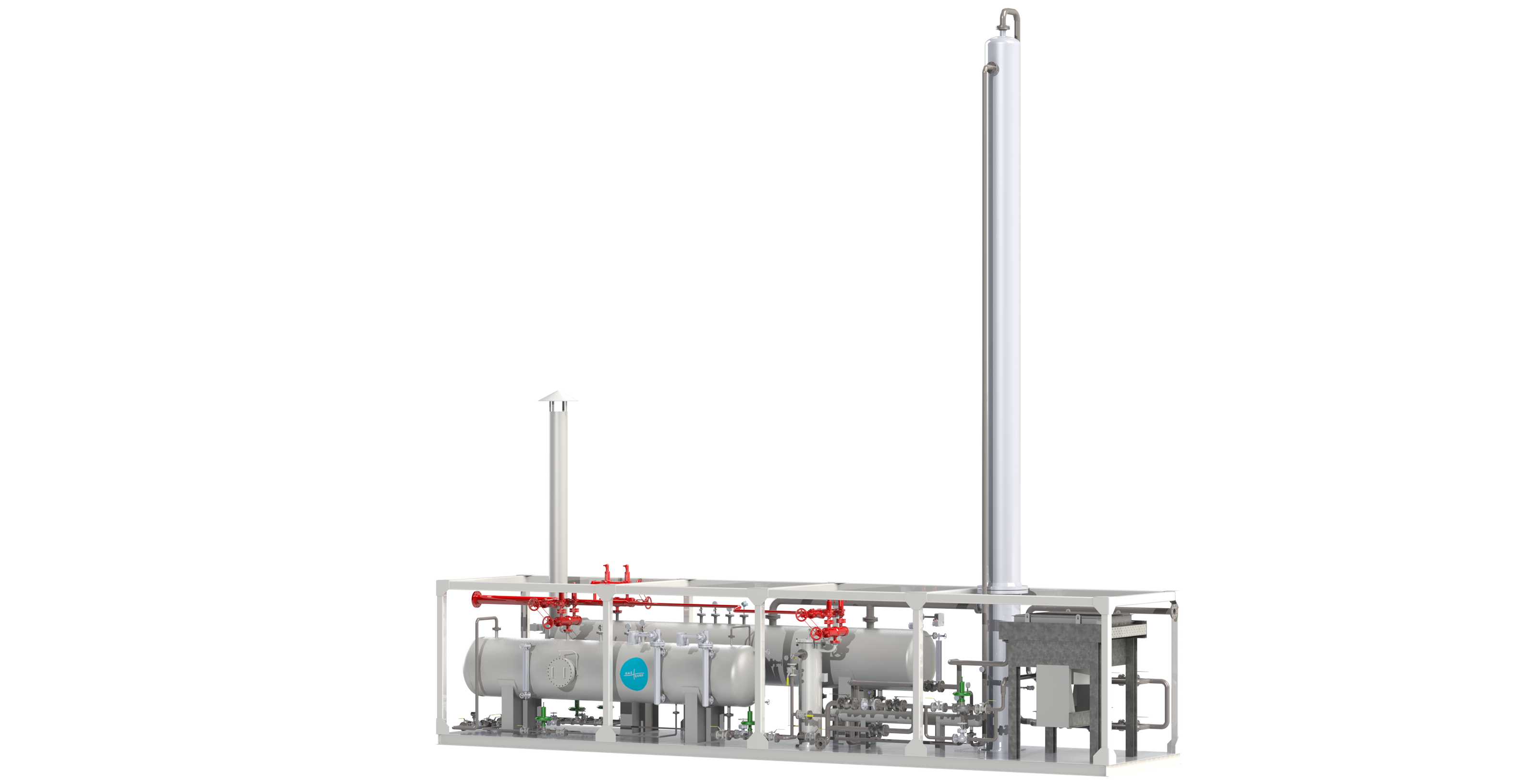
Low temperature condensation (LTC) process description
Complex gas treating unit of 200 scmd (2,19 billion scm per year) was developed by GazSurf as a ubiquitous solution based on the vast experience of our engineers’ team. We’ve combined all of the advantages of previously built units into this one. The standardization and a good all-around design of our solution allows to fine tune it to the exact requirements of our customers, be it varying compositions and flows of the feed gas or the range of desired products.
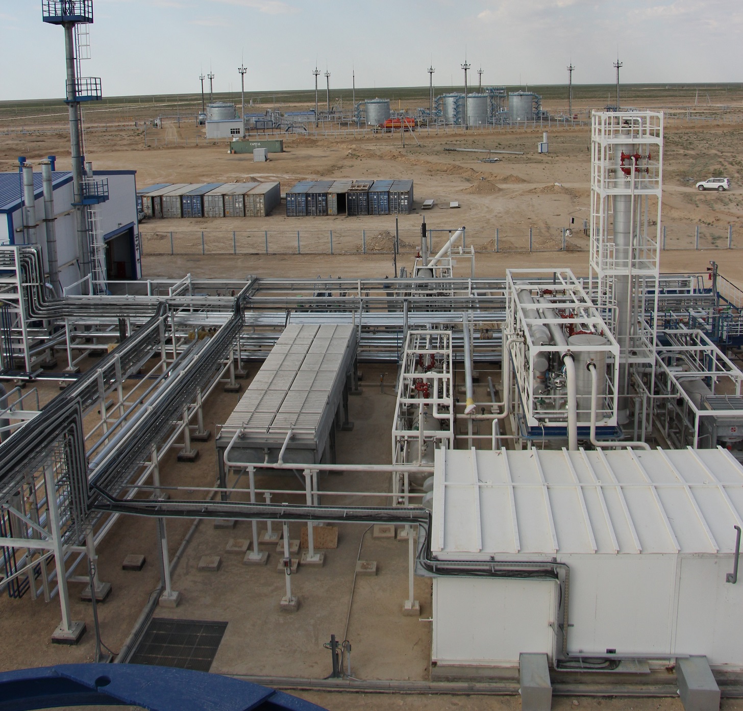
Projects
Engineering company «GazSurf»
Moscow, Volokolamsk highway, 1, building 1
+7 (495) 929 71 48 | info@gazsurf.com