Glycol drying
Application
The basic function of a glycol dehydration unit is to remove water vapor from natural gas streams to an outlet water content meeting various pipeline specifications.
The most common natural gas dehydration method is the absorption of water vapor into the liquid desiccant, Triethylene Glycol (TEG) or Diethylene Gtycot (DEG). ln addition to TEG and DEG, Tetraethylene Glycol (TREG) and Ethylene Glycol (MEG) are also available as liquid dessicants. Low freezing temperature of Water-EG/TEG mixtures allows their usage as hydrate inhibitor in the dew point control units. TEG dehydration units have usually a very low pressure difference defined only by the pressure difference of the absorber contactor.
Dehydration of CO2 streams can be also performed on the glycol dehydration units.
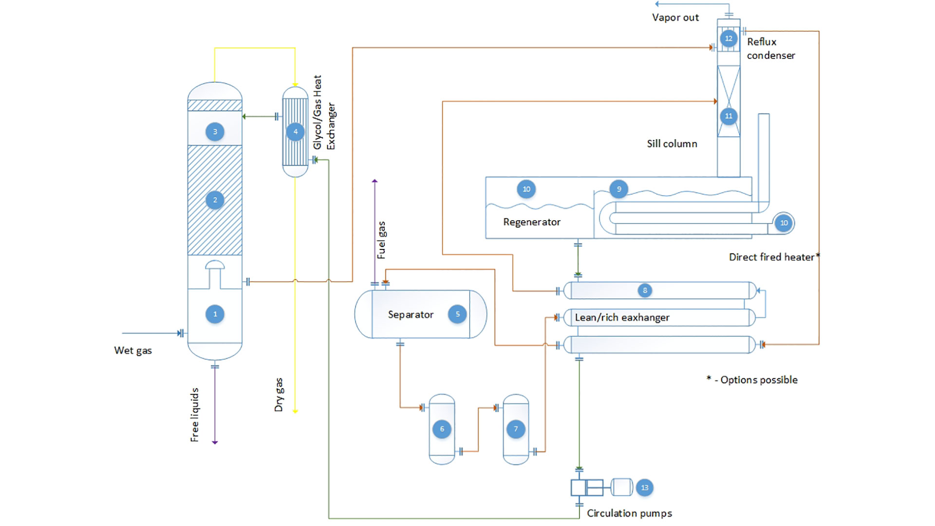
From the scrubber section, the wet gas enters the absorber (2) where the Lean TEG contacts the gas and absorbs the H2O. Depending on the customer specification this section can be based on either structural packing or on bubble cup trays
The dehydrated gas stream exits the absorber contact section and flows upward through the extended disengagement stage (3) prior to final separation and exits through the top outlet.
From the glycol contactor the dehydrated gas enters the glycol/gas heat exchanger (4) and cools the lean glycol flowing to the glycol contactor
The water rich TEG is level controlled from the glycol accumulation section of the contactor to the reflux condenser (12) section of the still column (11) where the cool TEG provides a reflux source to reduce TEG losses from the Still Column.
From the Reflux Condenser (12), the TEG continues to the Lean Rich HEX where it is preheated prior to entering the
In the
The Rich TEG is level controlled through the Particulate Filter (6), Carbon Adsorber (7), and the second stage of the Lean Rich HEX into the Still Column (11).
In the Still Column (11), the water vapor is stripped from the TEG and exits through the Reflux Condenser (12) and the Still Column. The partially stripped TEG flows downward to the Regenerator (10) where the TEG is re-concentrated at approximately 400°F (204.4°C) prior to flowing into the TEG Surge section. Fire tube (14) provides the heat required for the process (natural or forced draft burner).
Lean TEG exits the Surge. TEG flows through both sections of the Lean Rich HEX (8) before being pumped to the TEG / Gas HEX (4) where TEG is cooled to within 10°F of the gas temperature exiting the Absorber.
GazSurf Solutions
Key benefits
Durability
- Continuous process based on water absortion into the TEG solvent
- Absence of batch oscillations
- High durability due to redundant glycol pumps and control elements
- Shell and tube glycol/glycol exchanger with low temperature approach
- Fully automatic independent burner management system (BMS)
- Automatic glycol bypass system for the pump start-up
- Stainless steel tubes for steel condenser in standard design
Efficiency
- Low glycol losses due to the glycol/gas heat exchanger
- Glycol/gas heat exchanger bypass line for precise control of the glycol temperature
- High temperature
3-phase separator increases striping rate of light HC form TEG solution lowering overall rate of emission - 87% heat efficiency (with forced draft burners)
- 99.6 mass % TEG concentration without use of stripping gas
Flexibility
- Structural packing with 10 to 1 turndown ratio
- Modular, skid mounted design
- Non permit load skid size
- Pneumatic or electric driven control elements
- Single skid design (for regeneration units up to 20 GPM)
- MEG and EG regeneration
Process description
Water saturated gas enters the scrubber section (1) of the glycol contactor, where free liquids are separated and level controlled to storage. Free liquids are separated to prevent glycol contamination and subsequent damage to the regenerator.


Projects
Engineering company «GazSurf»
Moscow, Volokolamsk highway, 1, building 1
+7 (495) 929 71 48 | info@gazsurf.com